In this article, we are going to design a 10 Watt amplifier, to which an 8-ohm speaker will be connected as load. The required power will be delivered to the load by using an operational amplifier IC LF351 and two power transistors, TIP127 and TIP122.
How to design a Power Amplifier Circuit Using Power Transistors?
Now, as we know the abstract of our project, let us move forward and test the circuit after making the component list.
Step 1: Gathering The Components
Before starting a project, one must know what components he is going to need while working either it is a hardware component or computer software. An excellent approach that one can adopt to start a project is to make a complete list of all the components that he is going to use in a particular project. We can save a lot of time while working on a project if we have this list of components. So, a complete list of components that we are going to use in this project is given below:
Step 2: Circuit Design
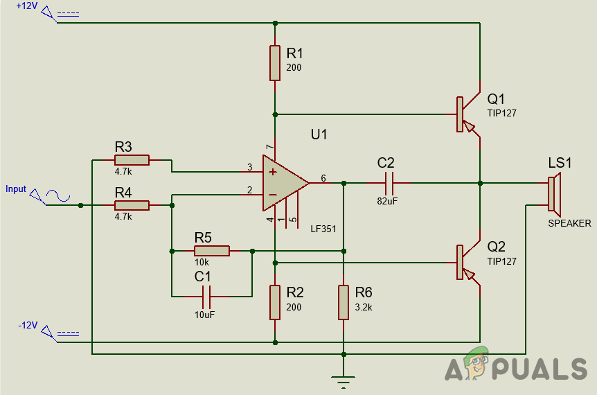
Usually, a Power Amplifier is the last block in an amplifier chain system. It is directly connected to load. Usually, voltage-controller amplifiers and preamplifiers amplify the input signal before sending it to the power amplifier. In Audio Amplifier Systems, most of the time, the load used is a Loud Speaker. Load impedance plays an important role in the output of the power amplifier. So, a proper load must be selected while connecting on the output terminal of the circuit. The LM351 is an integrated circuit that will amplify the input signal. Two power transistors are used that will provide the necessary power amplification. The transistors directly take the power from the power supply and give them to the load. As the input signal is AC, it will change its polarity. So both transistors will help to provide the power amplification to the opposite pole i.e., TIP127 will provide the power amplification to the positive peak and the negative peak will be provided power amplification by the TIP122.
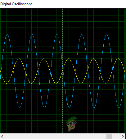
Step 3: Simulating The Circuit
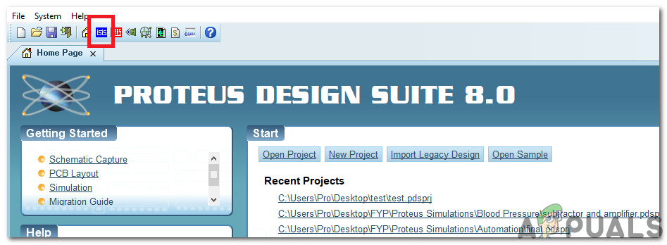
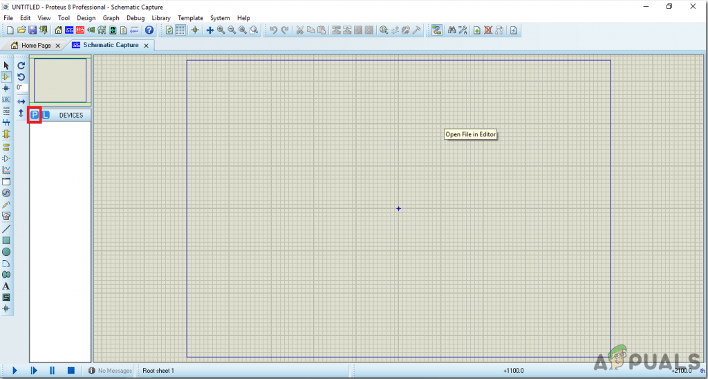
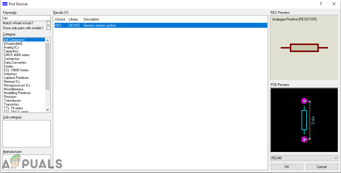
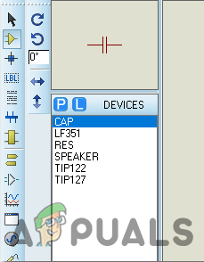
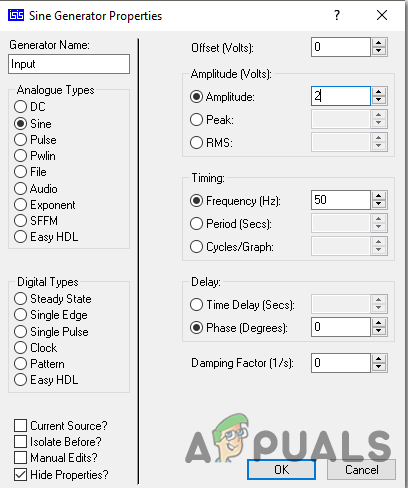
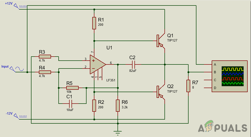
As we know have a complete list of all the components that we are going to use in this project, let us move a step ahead and test the circuit. Before making this circuit on hardware, let us do the simulation of this circuit on a computer software first. Simulating a circuit on software before implementing it on hardware is an excellent approach because it makes us assure that the circuit works perfectly fine and if there are some drawbacks, they can be corrected immediately on the computer. The software that we are going t use for the simulation purposes is Proteus. This software allows us to design a circuit on the computer and test its output by giving it an appropriate input. To simulate the circuit, go through the following steps:
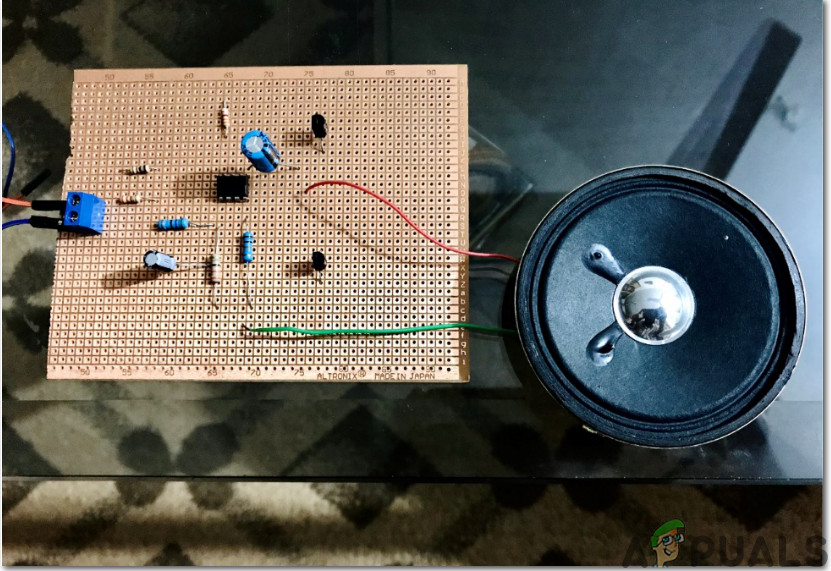
Step 4: Making The circuit
Now as we have simulated the circuit, let us make the hardware of this project on Veroboard. To implement this circuit on hardware, go through the following steps. One thing must be kept in mind that all the components must be placed close to each other and the circuit should be compact. So this was the whole procedure to make a power amplifier circuit. Now you can enjoy making this circuit at home.
How To Make An Intercom Circuit To Exchange Voice Signal Between Two Points?How To Make a Pickpocket Alarm Circuit?How To Make A Cell Phone Detector Circuit?How To Make A Metal Detector Circuit?