How To Assemble Light Dependant Resistor With Other Electronic Components?
The best approach to start any project is to make a list of components and going through a brief study of these components because no one will want to stick in the middle of a project just because of a missing component. The PCB Board is preferred for assembling the circuit on hardware because if we assemble the components on breadboard they may detach from it and the circuit will become short hence, PCB is preferred.
Step 1: Components Needed (Hardware)
Step 2: Components Needed (Software)
After downloading the Proteus 8 Professional, design the circuit on it. I have included software simulations here so that it may be convenient for beginners to design the circuit and make appropriate connections on the hardware.
Step 3: Studying The Components
As we now know the main idea behind the project and we also have a complete list of all the components, let us move one step ahead and go through a brief study of all the components. Light Dependent Resistor: An LDR is a Light Dependent Resistor which varies its resistance with the intensity of light. An LDR module can have an Analog output pin, Digital output pin or both. the resistance of the LDR is inversely proportional to the intensity of light which means greater the intensity of light, lower the resistance of LDR. The Sensitivity of the LDR module can be changed by using a potentiometer knob on the module. Power Transistor: A transistor can perform two tasks. In a circuit, it can work as an amplifier or as a switch. If it is working as an amplifier it takes a very little amount of current from the input side and amplifies that current at the output side. If it is working as a switch a tiny electric current that flows through one part of the transistor can make the bigger current flow through the other part of it. A normal transistor is used in simple circuits where a small amount of current is handled and a power transistor is used in complex circuits where we deal with a large amount of the current. A power transistor can carry large amounts of current without blowing up. Usually, the power transistors have heat sinks installed in them so that they may absorb excessive heat and avoid the heating up of the transistor. Printed Circuit Board: The PCB board is used in designing the electronic circuits. A thin layer of copper foil is present at the top of the PCB that is responsible for conductivity. PCB can be one-sided, double-sided or multi-layer. The chemical etching that is explained below divides that copper layer into separate conducting lines named as traces. A circuit is made on software firstly and then after getting the print out of that circuit, it is pasted on the PCB board with the help of Iron. The major benefit of a PCB is that the components are soldered on the board and they are not detached from it until they are de-soldered manually. A BC547 is an NPN transistor. So when the base pin is held at ground, the collector and emitter will be reversed and when the signal is provided to the base the collector and emitter will be forward biased. The gain value of this transistor ranges from 110 to 800. The amplification capacity of the transistor is determined by this gain value. We cannot connect the heavy load to this transistor because the maximum amount of current that can flow through the collector pin is almost 500mA. Current is to be applied to the base pin to bias the transistor, this current (IB) should be limited to 5mA.
Step 4: Understanding The Working Principle
The circuit is powered by a 9V DC battery. However, an AC to DC adapter can also be used to power this circuit because our requirement is 9V DC. The transistor BC547 is working in a saturation mode in this circuit. They are used for switching purposes in this circuit and they are responsible for powering ON and OFF the LEDs. There are twenty-five High Power LEDs in the circuit hence a power transistor is used here because it can handle a large amount of current and a heat sink is installed on it so, that the heat is dissipated in the air through that heat sink and the transistor isn’t heated up. The brightness of these High Power LEDs is equivalent to a fluorescent bulb that is enough and enlightens the room. The circuit will be assembled on PCB and the LEDs should be placed at a reasonable distance so that there are no chances of short circuit and the light is very well distributed in the room.
Step 5: Working Of The Circuit
The circuit is designed in such a way that the High Power LEDs are responsible for controlling the light intensity of the circuit. The Light Dependent Resistor plays a vital role in the circuit. It is responsible for turning ON and OFF the LEDs. The LDR follows the principle of photo-conductivity. The resistance of the LDR varies when light falls on it. When the light falls on LDR it’s resistance decreases and when it is placed in the dark it’s resistance increases. Hence, the switching of the LEDs depends on the resistance of the LDR. Twenty-five LEDs are used in the circuit. In the first connection, five LEDs are arranged in series and along with that five parallel connections are made and each connection has five LEDs arranged in series.
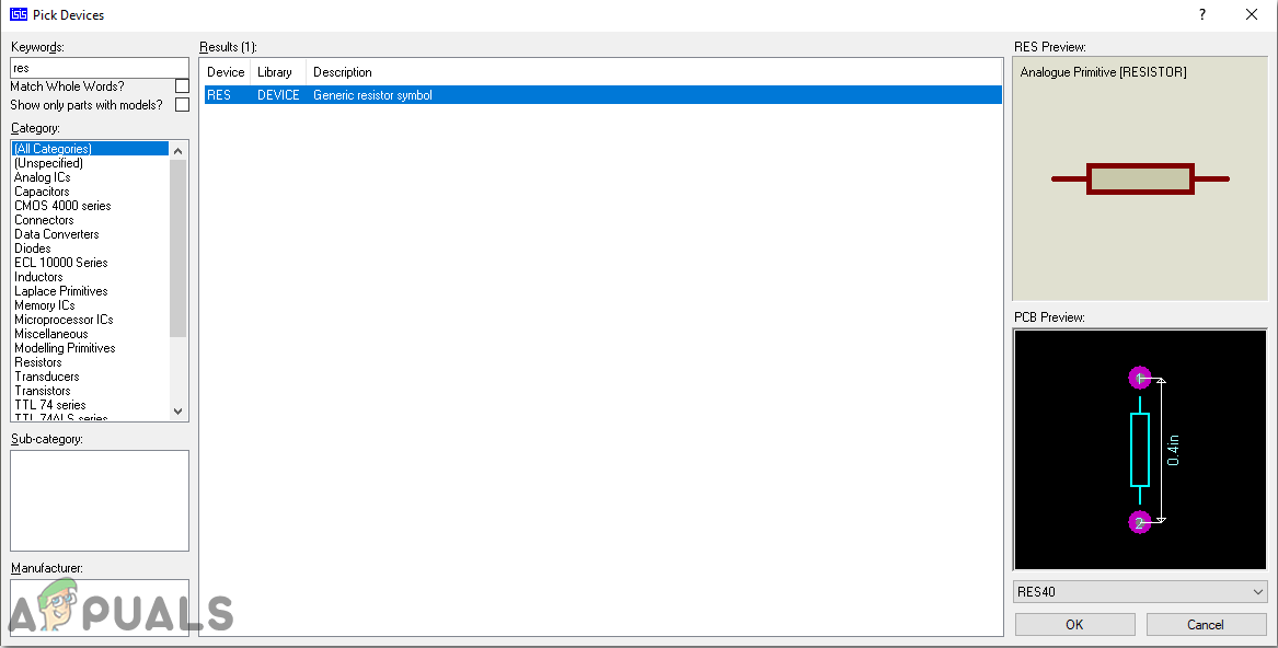
Step 6: Simulating the circuit
Before making the circuit it is better to simulate and examine all the readings on a software. The software we are going to use is the Proteus Design Suite. Proteus is a software on which electronic circuits are simulated:
Step 7: Circuit Diagram
After assembling the components and wiring them the circuit diagram should look like this:
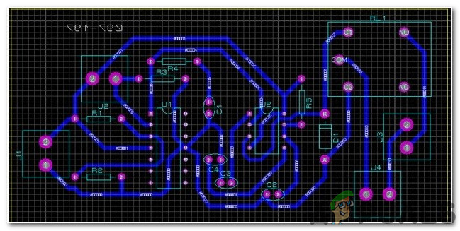
Step 8: Making a PCB Layout
As we are going to make the hardware circuit on a PCB, We need to make a PCB layout for this circuit first.
Step 9: Assembling The Hardware
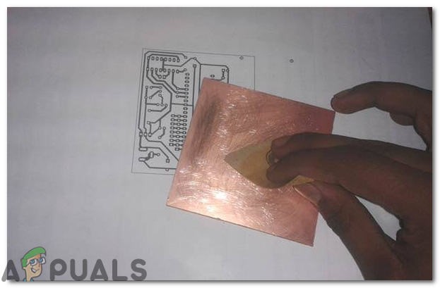
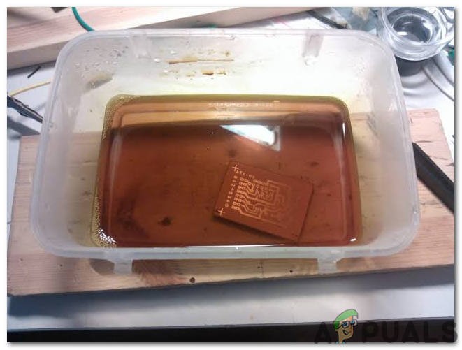
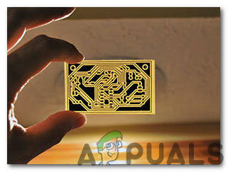
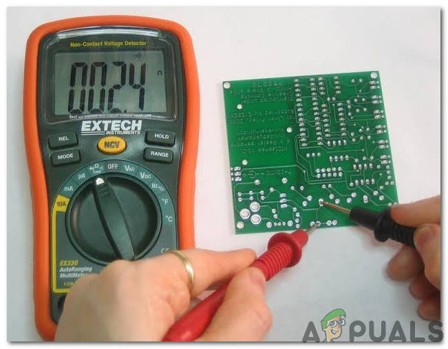
As we have now simulated the circuit on software and it is working perfectly fine. Now let us move ahead and place the components on PCB. A PCB is a printed circuit board. It is a board fully coated with copper on one side and fully insulating from the other side. Making the circuit on the PCB is comparatively a lengthy process. After the circuit is simulated on the software, and its PCB layout is made, the circuit layout is printed on a butter paper. Before placing the butter paper on the PCB board use a scrapper to rub the board so that the copper layer on board is diminished from top of the board. Then the butter paper is placed on the PCB board and ironed until the circuit is printed on the board (It takes approximately five minutes). Now, when the circuit is printed on the board, it is dipped into the FeCl3 solution of hot water to remove extra copper from the board, only the copper under the printed circuit will be left behind. After that rub the PCB board with the scrapper so the wiring will be prominent. Now drill the holes in the respective places and place the components on the circuit board. Solder the components on the board. Finally, check the continuity of the circuit and if discontinuity occurs at any place de-solder the components and connect them again. Apply hot glue gun on the circuit terminals so the battery may not be detached if any pressure is applied.
Step 10: Testing The Circuit
Now, our hardware is fully ready. Place the hardware at a suitable place on the side table of the bed and observe the working of the circuit during the night. If the LEDs are switched ON in the dark that means that our circuit is working properly. This hardware can also be fixed on the wall or any appropriate place near the bed so that there is ample light in the room and if someone wants to check the time on the mobile phone he/she can do that easily. The battery life may decrease after some time so, it should be continuously monitored and it should be replaced when it dries out!
How To Make Autonomous Plant Irrigation System?Night City Wire Episode 3 expands upon Night City and its Gangs; System…How To Design Panic Alarm Circuit For Home?How to Design A Touch Dimmer Circuit Using Arduino?